Alignment of the engine to the transmission
Updated:
Credits
Right up front I want to give credit to several people who went out of their way to help me figure this out (listed alphabetically by last name). Each of these people were instrumental in providing help and ideas, not to mention the numerous phone conversations and email communications discussing this tedious issue. Thank you, gentlemen.
- Charlie Cole of Zydeco Racing
- George Dockray
- Greg Field
- Gordon Kline of MG Cycle
- Charlie Mullendore of Antietam Classic Cycle
Background
It was in Guzziology (version 5.2, chapter 9, page 13) that I first read about improper alignment between the engine and transmission and the resulting clutch problems that arise. According to Dave Richardson, Bob Nolan discovered that some engines and transmissions are not properly aligned from the factory. This mis-alignment forces the clutch plates to be in constant non-concentric motion, thus leading to very rapid clutch wear. Bob created an alignment jig that allowed him to test for mis-alignment and to also correct it by re-drilling the holes for the alignment dowels (using over-sized dowel pins).
From anecdotal stories, I'd believed this problem to only affect some of the late 850 GT, 850 GT California, Eldorado, and 850 California Police motorcycles (as well as early Tonti-framed models).
The problem
However, I had never encountered this issue myself until I was asked to solve a very troublesome problem on a 1968 V700.
The V700 had an original V700 engine and original all straight cut 4 speed transmission. To the best of my knowledge, this V700 came from the factory with the engine and transmission that was in it when I first saw it. The owner complained of a very loud bird-chirping noise that would go away - only momentarily - when the clutch was dis-engaged and then re-engaged. The bird chirping noise was audible in all gears, though it was much more audible when the transmission was in neutral. The owner had previously installed new clutch components (three times) and the problem had not resurfaced until several hundred miles down the road.
The investigation
When I received the motorcycle I immediately confirmed the bird-chirping noise. It was loud. Very audible even with a helmet on and ear plugs inserted. It sounded like dry metal rubbing on dry metal and, indeed, resembled the chirping of a bird. Something was definitely wrong.
I did all the usual checks to try to rule out the easy possibilities:
- I removed the generator belt to make sure the generator bearings weren't squealing.
- I removed the generator and bracket entirely to make sure the generator bracket wasn't cracked and making the noise.
- I removed the generator pulley from the front of the crankshaft to make sure it wasn't rubbing on the timing cover.
- I removed the complete throw out bearing assemble to make sure the throw out bearing hadn't gone bad.
- I removed the clutch push rod to make sure it wasn't noisily rubbing on the pressure plate cup.
None of these tests made any difference in the bird chirping sound. Next, I removed the starter and directed a spray of WD-40 on the clutch input hub. Immediately upon start up, the bird chirping was gone. Aha! The splined interface between the clutch input hub and the clutch plates is what is causing the problem. But why?
I removed the engine and transmission from the frame and disassembled the clutch assembly, carefully inspecting and meticulously measuring each part as I went (even measuring the depth of each spring recess in the pressure plate and flywheel). I could detect no problems with the ring gear, flywheel, pressure plate, springs, or pressure plate cup. The clutch input hub, clutch plates, and intermediate plate, on the other hand, did show signs of wear (and all of these parts were brand new only 2,500 miles earlier).
- The front clutch plate (as viewed from properly astride the motorcycle) showed very little wear from new. Both sides were in fantastic condition. The splines were in very good shape.
- The rear clutch plate, however, was nearly used up. In 2,500 miles, it had shed enough friction material to be at it's minimum thickness. Given how rapidly the clutch material wore, the dust could not evacuate the flywheel assembly quickly enough. Indeed, the dust from the clutch disc was packed in around every spline and tooth and open area within the entire clutch assembly. I've never seen that much clutch dust before. It was incredible. This dust had to be acting as a grinding compound, exacerbating the problem. Oddly, the splines were in very good shape.
- The splines on the clutch input hub showed some unusual wear patterns. First, the rear most splines showed more wear than the front most splines. That is expected, given the observed clutch plate wear. Second, the wear patterns were not uniform around the entire circumference of the clutch input hub. That is, the wear was noticeably worse on one side than it was on the other side. Furthermore, the wear patterns were not the same between where the hub would interface with the front clutch plate an the rear clutch plate. Odd, indeed.
- The intermediate plate was warped conically and showed signs of friction induced heat in some areas, but not others. It had obviously been slipping.
Tests for alignment
I contacted Greg Field because I knew he and Bob Nolan are friends. I wondered if Greg could contact Bob for me and see if I could get some information on the alignment jig, or even borrow it. Since Bob is in poor health, Greg suggested I'd have better luck contacting George Dockray up in British Columbia, Canada. George had previously borrowed Bob's jig and had made a copy. A couple of quick emails with George and the jig was sitting on my workbench ready to test.
George's jig was set up to work with a clutch input hub having 4 mm deep splines. Since 4 mm deep splined clutch input hubs are exceedingly rare for 4 speed transmissions, I took George's jig down to my machinist and had him make a copy that would work on both 2 mm and 4 mm deep spline clutch input hubs. Essentially, the jig is bolted to the flywheel (centered by the design of the jig) and then the clutch input hub (connected to the transmission) is placed inside the other end of the jig. I found this easiest to do with the bell housing studs removed and the engine resting on it's nose (bell-housing facing up).
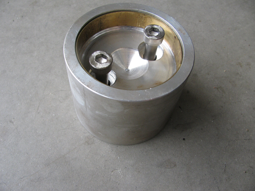
Photo courtesy of Gregory Bender.
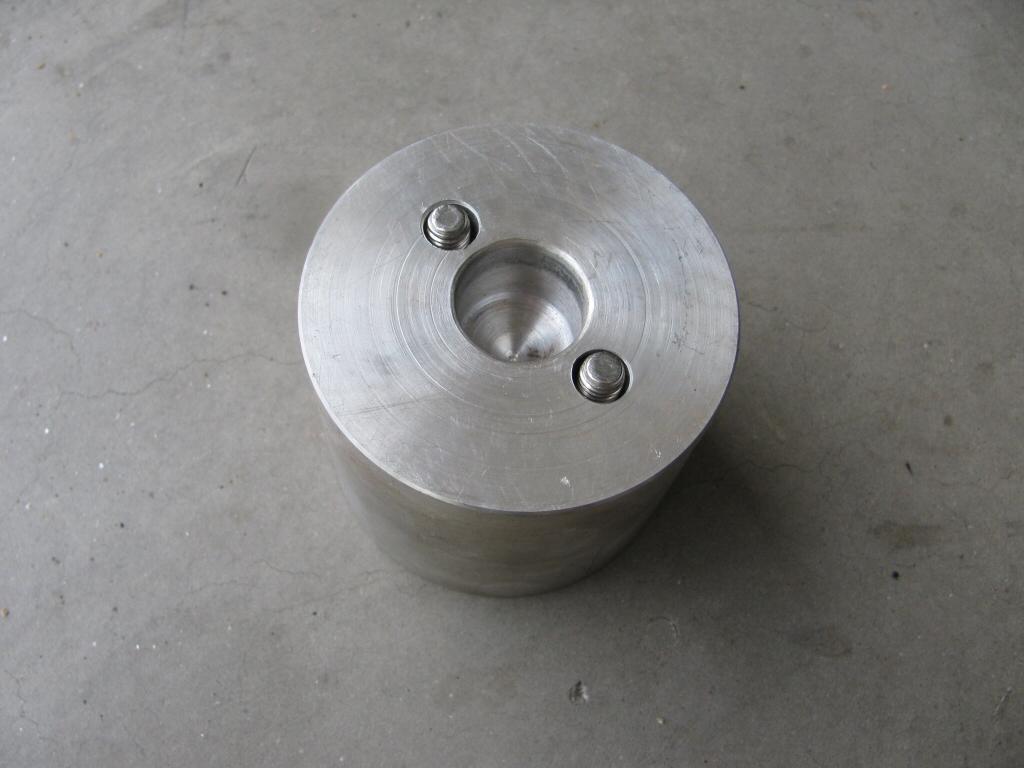
Photo courtesy of Gregory Bender.
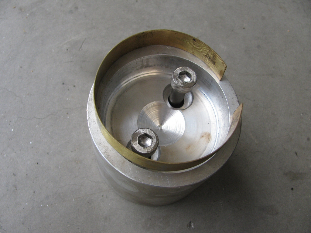
Photo courtesy of Gregory Bender.
Perhaps I wasn't using the jig properly, but I could determine no misalignment between the engine and the transmission using it. I know Bob and George have used theirs successfully, but I was unable to do so.
So, I came up with my own means of testing for alignment between the engine and transmission. Please note that my method only checks for alignment, it does not enable correction.
- I prepared the engine by removing the complete flywheel assembly. I placed masking tape over the end of the flywheel and coated the masking tape with Prussian blue dye.
- I prepared the transmission by removing the clutch input hub, the clutch push rod, and the complete throw-out bearing assembly.
- I placed a proper sized transfer punch (Harbor Freight item number 3577) inside the clutch shaft (input shaft to the transmission). Precision is important here, the shaft of the transfer punch must be perfectly centered inside the clutch shaft. In order to gain the accuracy I needed, I chose a slightly smaller diameter transfer punch, the wrapped a very even layer of tape around it to make up the difference.
- I bolted the transmission to the engine.
- I placed the clutch push rod in the end of the clutch shaft and used it to slowly and carefully push the transfer punch forward until the very tip of it made contact with the masking tape on the front of the crankshaft (Shining a light through the hole left by the absent starter motor).
- I then rotated the engine through a complete revolution (or a bit more).
- I removed the transmission from the engine and noted the pattern made by the transfer punch in the Prussian blue dye.
I repeated this test numerous times until I was very confident in the technique and the results I achieved. I made four tests as pictured below. You may notice some size and scale differences in the photos below. You may also notice that some of the single points
are larger than others - that is primarily due to the transfer punch being pushed closer into the masking tape. Rest assured the resolutions you are viewing are much larger than normal and that the single points really are single points.
Test 1: original V700 engine with the original V700 transmission
This was the first test I performed. Note the mark is a circle when it should be a single point. The diameter of the circle is 1.5 mm.
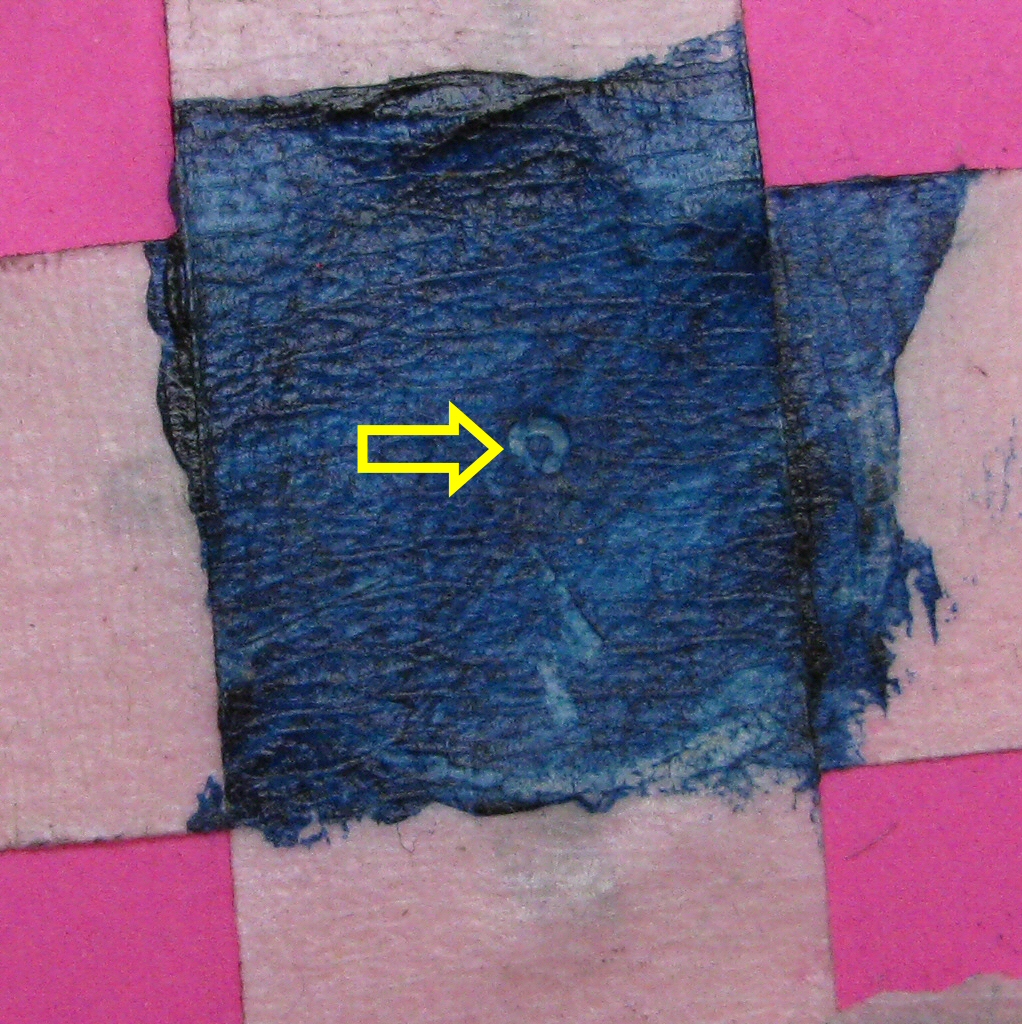
Photo courtesy of Gregory Bender.
Test 2: Quota engine with the Quota transmission
My Quota was conveniently disassembled at the same time for some work. I was thrilled to find a single point.
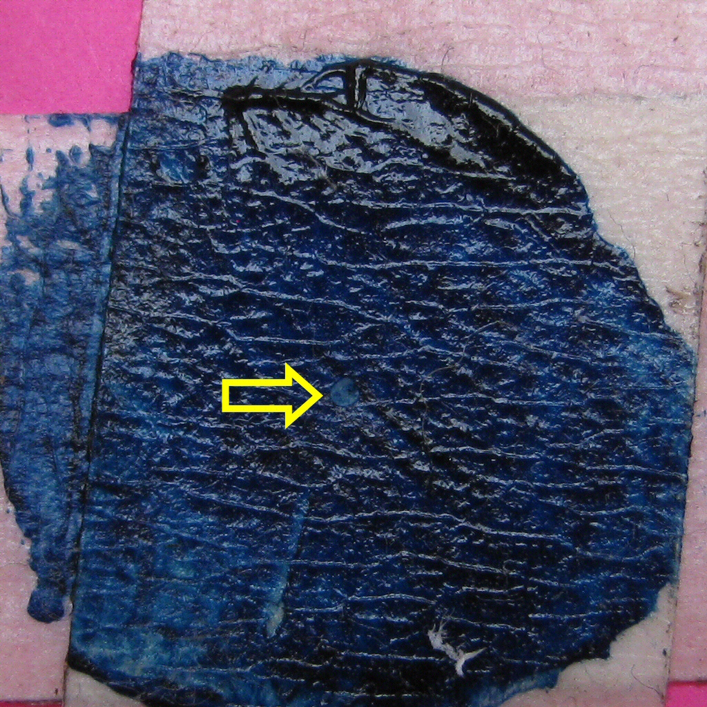
Photo courtesy of Gregory Bender.
Test 3: original V700 engine with another 4 speed transmission
I had another 4 speed transmission sitting on the shelf. I bolted it up for a test and found a single point.
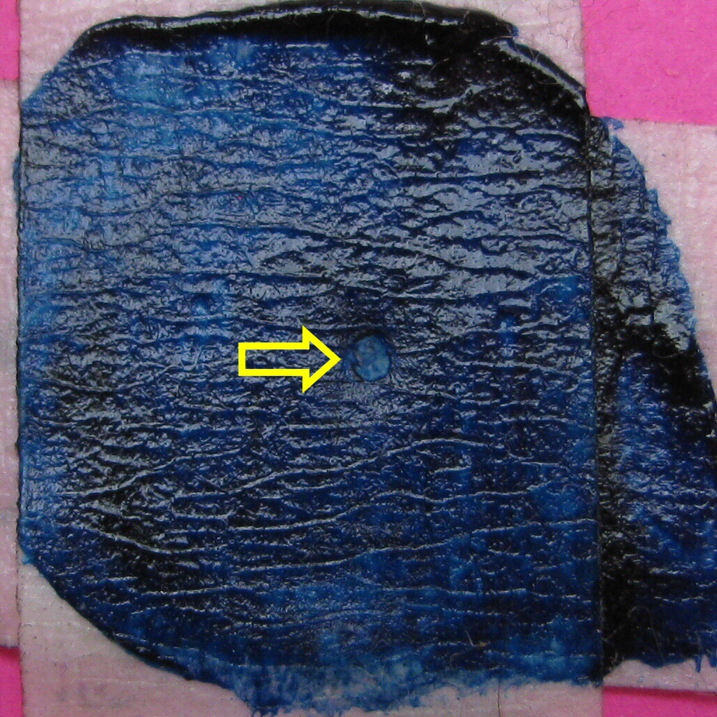
Photo courtesy of Gregory Bender.
Test 4: original V700 engine with the Quota transmission
For grins, I bolted up my Quota transmission and found another single point.
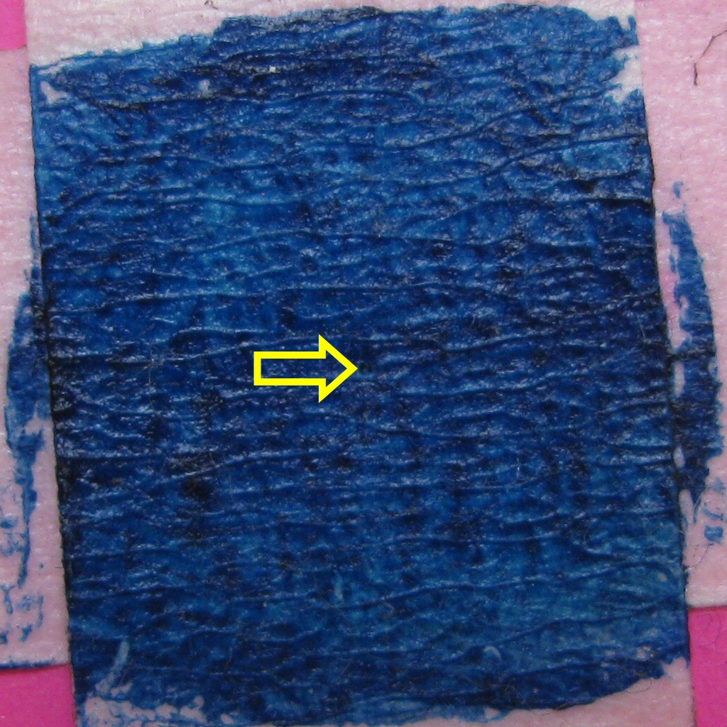
Photo courtesy of Gregory Bender.
Aha! I learned something. First off, I learned that the original V700 engine is not aligned properly with the original V700 transmission. Good, we have a cause for all the trouble. Second, I learned that other transmissions align properly with the original V700 engine. This means the culprit is the original V700 transmission, and not the original engine. From this limited data, I would guess that the Moto Guzzi factory drilled all of the engine cases the same, then later aligned each transmission to the engine. This is only a guess, but it seems to follow the data.
Time to fix the problem
I suppose I could have hired a machinist to figure out how to align, drill, and fit over-sized dowel pins (I knew that sort of accuracy was beyond my skill level). That would be expensive and that there was a very real chance of error. Instead, I sourced a good used 4 speed transmission case from Charlie Mullendore of Antietam Classic Cycle. After checking that transmission case for alignment with the original V700 engine, I sent the original transmission and the replacement transmission case to Charley Cole at Zydeco Racing for transfer of the innards, proper set up, and shimming.
What I don't know
What I didn't learn in all of this is the root cause of the mis-alignment. Sure, I believe the root cause is with the transmission. However, I do not know if the mis-alignment is due to:
- Parallelism between the crankshaft and the clutch shaft. That is, both shafts rotate in parallel axis, but are simply rotating non-concentric.
- Non-parallelism between the crankshaft and the clutch shaft. That is, the shafts do not rotate in parallel. Given the pattern of wear on the clutch input hub, I suspect this may be the case.
- A combination of parallelism and non-parallelism between the crankshaft and the clutch shaft